Home » Pneumatic Grippers » O-Ring Assembly Machines
O-Ring Assembly Machines
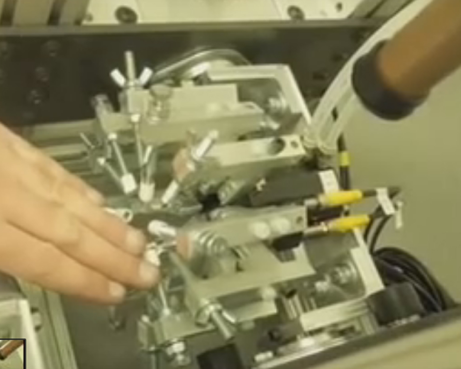
Automation of o-ring assembly requires many parts to work as a whole. Typically a vibratory bowl will separate the o-rings, feed them down a track into a dead nest for the o-ring gripper to pick and place the seal on the parts.
Pneumatic double acting cylinders require a four way two position valve to operate them. Combining these actuators can yield an efficient robotic pick and place system for lean manufacturing. Our fast deliveries bring your inventory costs down and keep your production schedule up.
All models are designed to facilitate part ejection and/or part seating; ideal when an ejector is needed for part placement or when a seal is to be placed along a shaft.
Application
Assistance of automated O-Ring or Seal placement/installation
Range of Capability
Spreading and placement of O-Ring or Seals .250” diameter and larger
Important Features
- The expander jaws travel in the t – slot bearing guides to provide exceptional resistance to all moment loads.
- A large piston provides strong expansion force to expand large cross section O-ring and hard durometer materials.
- Rapid cycle times. Semi & fully automatic seal placement.
- Incorporate in full assembly systems or stand alone work- stations.
Shop all O-Ring Assembly Machines
Showing all 3 results
-

Features & Benefits
Supported T-Slot jaws help prevent jaw breakage while offering superior load/bearing performance.
Spreading and ejector jaws operate independently, allowing for exact timing of ring installation.
True parallel jaw motion, compact design, and adjustable stroke allow for easy tooling.
Weight 1.25 lbs
Design: Parallel, Double Acting, Synchronized Sealed JawsStroke: Spread 0.6 in. adj. [15 mm]
Ejecting 0.25 in [6.3 mm]Gripping Force Per Jaw
Spreading jaws have 14-55 lbs. force [each] @80 psi *
Ejector jaws have 80 lbs. force [combined] @80 psi. -
-
Product Inquiry
"*" indicates required fields
Product Categories
Additional Information
O-Ring Gripper Italiano
O-Ring Gripper Espanol
Design Details
Pneumatically operated gripping, spreading and placement of Seals or ‘O’-rings [with the assistance of automated ‘O’-Ring placement machines] via a dual piston mechanism, one being housed within the other yet independently functioning/operating.
Per an association of connecting rods and piston the spreading jaws operate in an in & out, or open and close motion, while the ejector jaws are piston operated [only] during the ejection/extension part of the cycle with a spring operated return/retraction.
O-Ring Assembly Features
All models are designed to facilitate part ejection and/or part seating; ideal when an ejector is needed for part placement or when a seal is to be placed along a shaft.
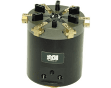
- AGP-6-OR features [6] spreading jaws and [6] ejector jaws. Lightweight and versatile.
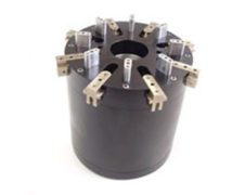
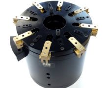
- AGP-8-OR & AGP-10-OR each feature [8] spreading jaws and [8] ejector jaws, [plus thru-hole design].
- T–slot designed bearing guides provide spreading jaws resistance to moment loads.
- Large diameter pistons provide adequate force for spreading large ‘O’-Ring cross sections even in hard durometer materials.
- Vertical or horizontal use.
- No lubrication of ‘O’-Rings necessary while installing.
The further outward the spreading jaws are utilized during the stroke cycle, the greater the amount of force applied to the ‘expansion of the O’-Ring/Seal.
The action/angle of the connecting rods and relative internal mechanisms apply an ever increasing force along the spreading jaws as they move outward.
This feature should be taken into account during design stages of assembly machines.
Models: [3] sizes available
- AGP-6-OR handles up to 3” i.d. seals or rings.
- AGP-8-OR handles up to 12“ i.d. seals or rings.
- AGP-10, the new and largest model, is a very robust, heavy duty unit, and without limitation can handle any size ring with the assistance of specifically designed spreading fingers.
Note: AGP-8 & AGP-10 offer thru-hole design, allowing for installation of seals and rings along the lengths of shafts or columns.
- AGP-8 has a 1.500” thru-hole.
- AGP-10 has a 2.250” thru-hole.
Videos
Function
- Pneumatic actuated grippers utilizing [2] independent pistons. Spreading jaws are double acting. Ejector jaws are single acting. Applying air pressure to the former actuates the parallel jaws, expanding an ‘O’-ring or Seal into an octagon shape. An ‘O’-ring or Seal stretched in this manner creates less deformation than other processes common to installation. [The expansion stroke can be adjusted via easily-accessible set-screw[s].
- When the ‘O’-Ring/Seal is expanded and positioned for installation, air pressure is applied to the remaining piston. Per this process, ejector jaws will dislodge, [pushing], the ‘O’-Ring/Seal from the spreading jaws and onto the assembly part.
O-Ring grippers can be tooled to accommodate all types of rings and seals, from very small to very large. It is up to the imagination of the engineer to utilize the motions provided by these designs to achieve a desired outcome.
AGI does not design nor produce ‘fingers’ or ‘jaws’ for end customer applications.
Sensing: Per all models, available for end-of-stroke on both spreading and ejection.
Dimensions/Forces
AGP-6-OR is 2.500” dia. x 2.700” tall.
Spreading jaws have 14-55 lbs. force [each] @80 psi *
Ejector jaws have 80 lbs. force [combined] @80 psi.
AGP-8-OR is 5.000” dia. x 5.000” tall.
Spreading jaws have 70-462 lbs. force [each] @80 psi.*
Ejector jaws have 320 lbs force [combined] @80 psi.
AGP-10-OR is 7.000” dia. x 7.000” tall.
Spreading jaws have 112-1230 lbs. force [each] @80 psi.*
Ejector jaws have 750 lbs. force [combined] @80 psi.
*Depending where in the cycle of stroke it is measured. The farther the spread or opening of jaws, the stronger the force. This exponential force {curved} applies to all AGP-OR Grippers. Also, keep in mind these are ‘no’-friction numbers. Every application will entertain a different coefficient of kinetic friction depending on finger design, {height & length}, and should be taken into consideration during design stages of assembly equipment.
-Usually available from stock.
-[2] and [3D] CAD available on our website.
Tips Regarding O-Rings & Installation
- A stretch greater than 5% on the O-ring I.D. is not recommended because it can lead to a loss of seal compression.
- A Groove depth is the machined depth into one surface, whereas a Gland depth consist of the groove depth plus diametrical clearance and is used to calculate seal compression.
- To create seal compression the groove depth must be less than the seal cross section. To compensate for this compression, the groove width must be greater than the seal cross section.
- Static applications are more tolerant of material and design limitations than dynamic applications.
- The maximum volume of the O-ring should never surpass the minimum volume of the gland.
- For reciprocating seals passing O-rings over ports is not recommended. Nibbling and premature wear and seal failure will result.
- The closer the application is to room temperature, the longer an O-ring can be expected to effectively seal.
- Avoid using graphite-loaded compounds with stainless steel, as they tend to pit the stainless steel surface over time.
- Before installation, make sure to lightly coat the O-ring with a lubricant that is compatible with the O-ring material, as well as with system chemicals.
- When using only one back-up ring, be sure to install it on the low pressure side of the O-ring.
- Static seal cross-sections are generally compressed from 10% to 40%, whereas Dynamic seals are from 10% to only 30%.
- When it is said that an elastomer is good for an application it is meant that some compounds which include that material are acceptable. Not All. For instance, some compounds of EP are good for brake fluid applications, but most are not acceptable.
- Material cost does not correlate with performance, it depends on the application.
- You must test all seals in their actual environment because every application is unique.
- DO NOT use a lubricant composed of the same material as the O-ring. For example, a silicone lubricant should NOT be used with a silicone O-ring.
- Resistance of elastomers to chemical attack is greatly reduced at elevated temperatures.
Repeated Stress Injuries
Authorities in the field of ergonomics agree that repeated stress on certain joints and tendons is likely to cause ailments such as tendonitis, arthritis and carpel tunnel syndrome. Companies, as a result, suffer soaring medical costs and production losses. AGI President, Millo Bertini, stated:
“One great advantage of implementing O-Ring Installation Assembly Tools is that workers place less stress on their hands.” A direct result is that repeated stress injuries are reduced… something both workers and their employers benefit from.”
When manufacturing workers sustain injuries, there are implications to productivity and scheduling. Manufacturing outfits that embrace new technologies are finding themselves ahead of the curve as a result of decreased injuries among their staff.
AGI has recently made significant investments in their manufacturing plant, making it possible for them to deliver products to customers with a short lead time, and at low cost. Implementation of new robotics devices now faster than ever, and with today’s price points, the benefits of automation are available for small and mid-sized manufacturing plants.
AGI’s O-Ring-Assembly Tools are available in three sizes to accommodate placement applications ranging from 3 inch and up. Both the AGP-6-OR (which has six jaws) and the AGP-8-OR (which has eight) are designed to facilitate part ejection and part seating and are ideal for applications where an ejector is needed after part placement. They are both equally functional when a seal needs to be placed down a long shaft. The AGP-10 can handle any size ring with the assistance of specifically designed spreading fingers.
As a result of independent piston technology and double-acting spreading jaws, O-Rings that are stretched by these pneumatic grippers suffer considerably less deformation than they would if installed through traditional assembly methods. And there is no risk of over-expansion, as the opening stoke can be precision-adjusted.