Design Guidelines for Pneumatic Gripper
When designing a robotic or automated assembly machine, applying a gripper correctly unit can make the difference in the reliability and productivity of the assembly machine system or robotic cell. Gripper calculations will vary depending on many factors such as, part acceleration, part weight, physical size, tooling length, tooling jaw style (encompassing grip or friction grip), tooling jaw material and the number of jaws that come in contact with the part.
Below are some fundamental factors to keep in mind when designing automated equipment with a gripper. Remember the gripper is the last part of the machine to handle the part being assembled, so careful consideration should be made.
Main considerations:
- Tooling jaw friction calculation using Coulomb friction (Ff = mFn) as a simple model where: Ff is force of friction exerted by each tooling jaw surface, parallel and opposite to the net applied force, m is the coefficient of friction, and Fn is the normal force exerted by each tooling jaw on each other. The maximum value of static friction that can be experienced through the surface of contact equals, where is the limiting coefficient of static friction and is the normal force.
- Gripping force factor calculation guidelines are made to ensure that the actuator mechanism will apply the proper force and prevent slipping or dropping or parts being handled, design for worst case conditions. More specific calculations are: mnf Fg = wgS where m = coefficient of friction, nf = number of tooling jaws, Fg = gripper force, w = part weight, g = gravity and S = safety factor (3 to 4 in a typical application, higher speeds will require a greater safety factor).
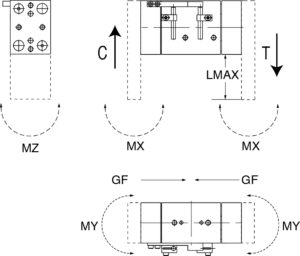
- Keep tooling finger length to a minimum to keep moment loads and forces to a minimum. The longer the tooling the greater the rotation forces are created at the gripper bearing reducing its force applied to the part or efficiency to translate piston force to jaw force. Longer jaw tooling will reduce useful life by causing excessive wear on the actuators moving components. Follow maximum finger length charts included in manufacture data sheet to maximize gripper life.
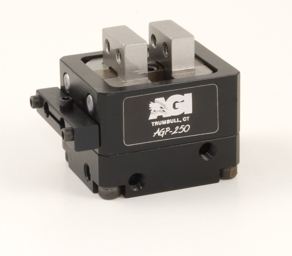
Pneumatic gripper selection
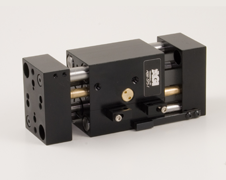
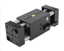
The two main styles of grippers are parallel and angular referring to jaw movement.
Parallel grippers are the most common due to the ease of tooling, adapt to various part sizes without changing tooling finger and can be used non-synchronous to allow jaws to comply and shift to work piece centerline.
Two jaw gripper are use in most of the applications since they are cost effective, can handle multiple shapes and sizes.
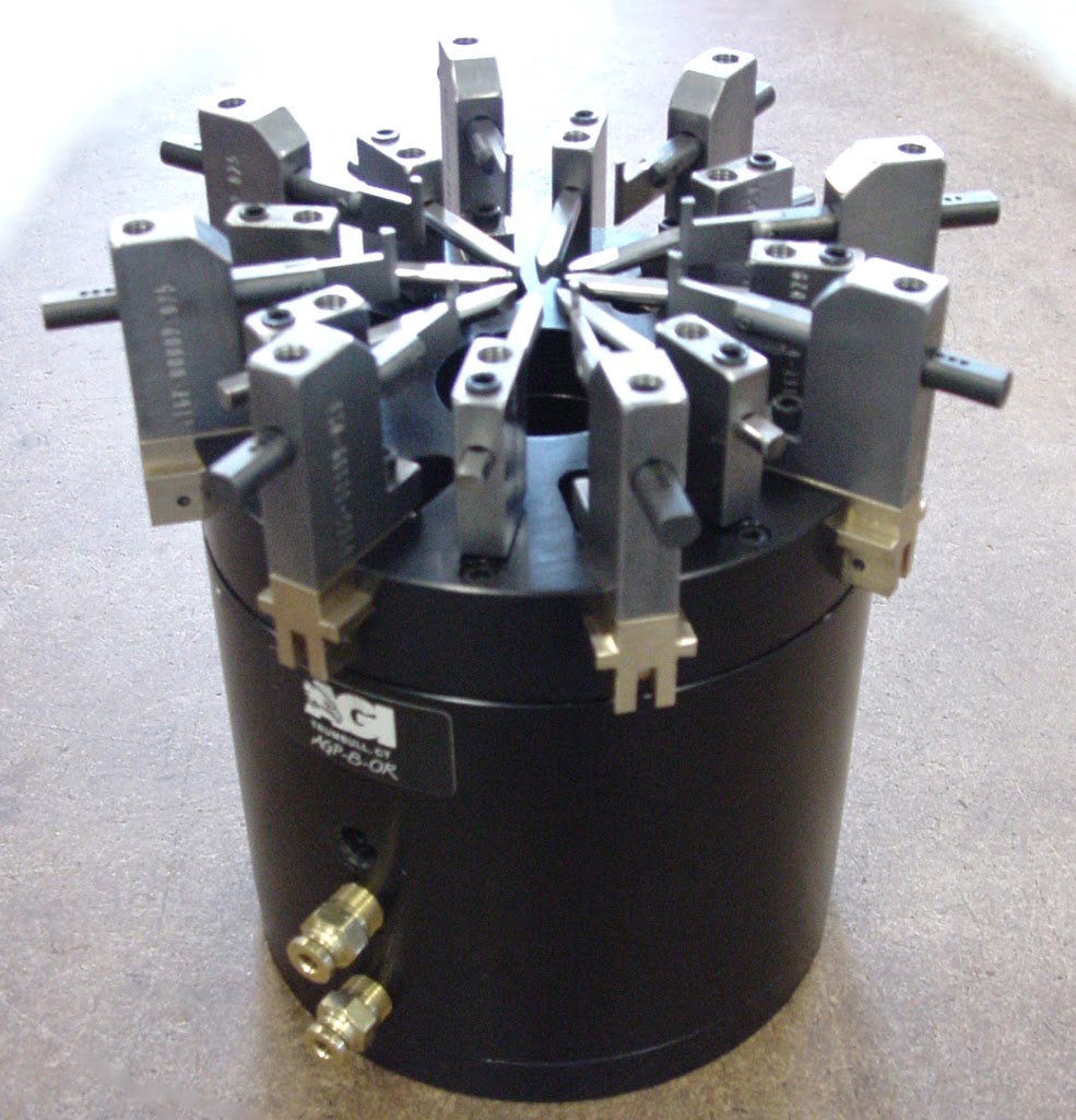
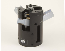
Three jaw grippers are mostly used on round parts that are handled axially and offer more gripping force with shorter strokes.
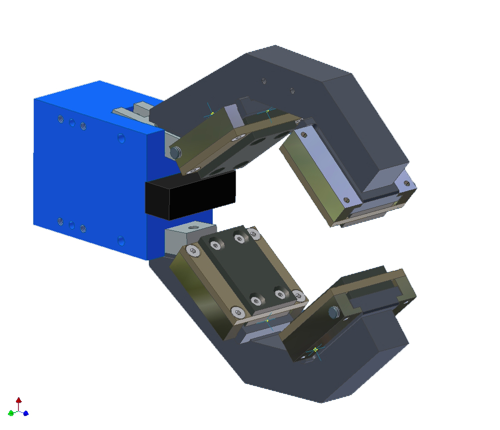
Angular gripper jaws swing an arch that can be adjusted to reduce the opening swing; usually they are dedicated to picking up one size part and useful where vertical space is limited.
They are also offered in two or three jaw configurations with synchronized jaw movement and come in fail safe (toggled locked jaw) or standard non locking types.
Angular grippers with 180 degree jaw travel need to take into account the inertial at the end of stroke, keeping tooling weight and acceleration down.
This can be accomplished by the use of light weight materials like aluminum, shorten tooling jaw as much as possible and the use of flow controls to reduce speed of tooling swing. The other types of standard grippers are made with a specific task in mind, such as the O-ring gripper to aid in the assembly of installing o-rings on parts or the single jaw gripper when a zero positions is needed.
These are basic tools and suggestions and every application is unique. The loads that grippers handle vary greatly do to part weight, size, speed of movement, material type, shape of tooling jaws and shop air pressure. This design guild is made to help you narrow down your selection and increase the reliability, productivity of the assembly machine system or robotic cell. To learn more concerning our assembly automation components, please contact us and we will help with your application needs.
P: 203-459-8345