Tips and guidelines on tooling o-ring gripper:
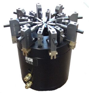
AGI O-ring grippers are designed to facilitate automated installation by spreading and ejecting the o-ring onto a part quickly, it can also be used for part seating applications. Via a vibratory feeder bowl, O-rings can be singulated and fed down a track to a dead nest fixture where the gripper can pick and place one ring at a time. These grippers can be also use in semi-automated or hand assist ergonomic assembly.
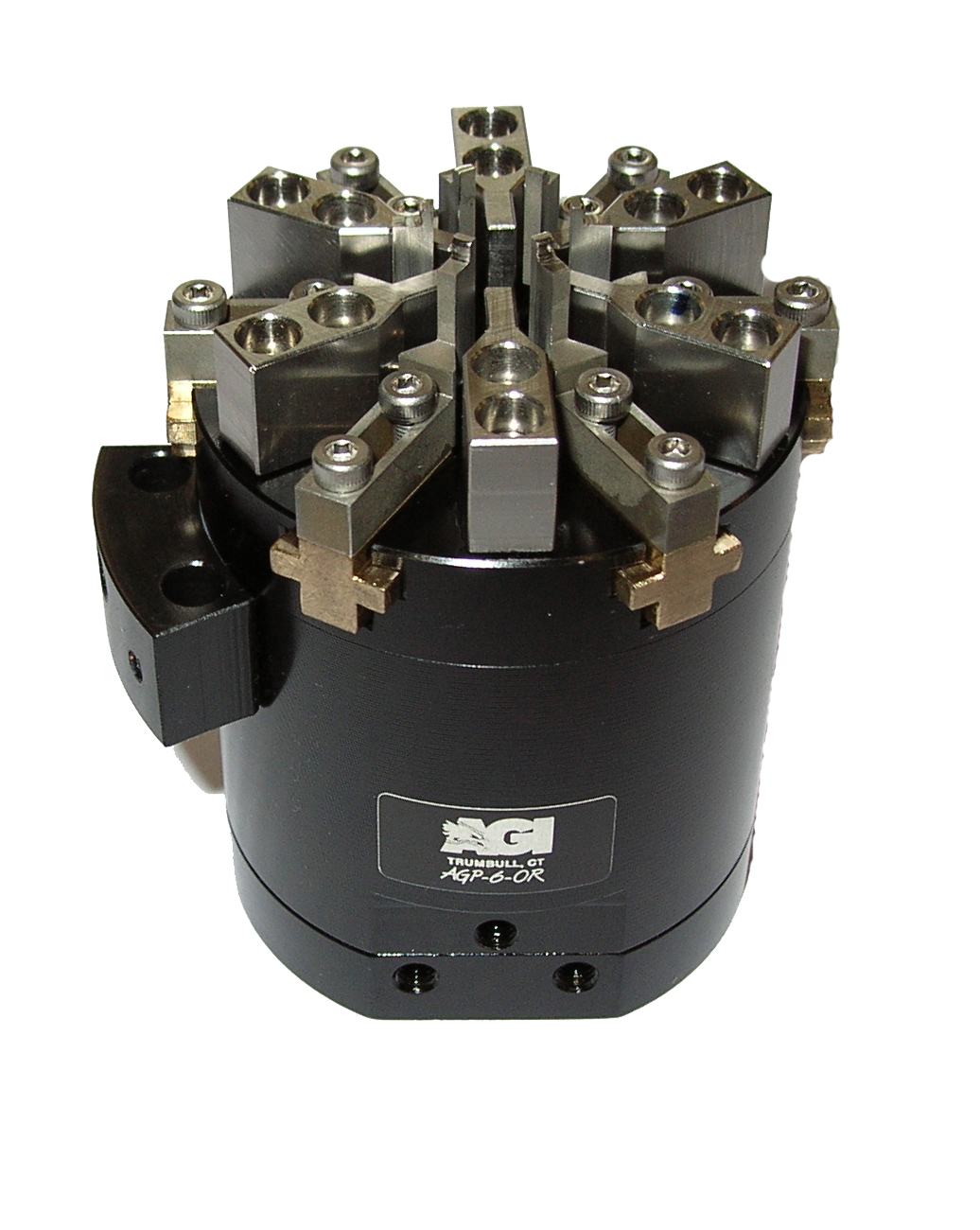
The advantage of using a six jaw gripper over a three jaw is that the O-ring requires less overall expansion and considerably less deformation during assembly process. Moderate stretching (below 20 percent) is recommended during the o-ring installation and a seal should never be expanded more than 50 percent of relaxed size.
Elongation properties primarily determine the stretch that can be tolerated during the o-ring installation and specification should be confirmed with the o-ring manufacturer. Elongation is also a measure of the ability of a compound to recover from peak overload and excessive stretch; this will shorten the life of most o-ring material. To keep the o-ring from over stretching, the adjustable spreading jaws offer a stroke adjustment for the opening or spreading action.
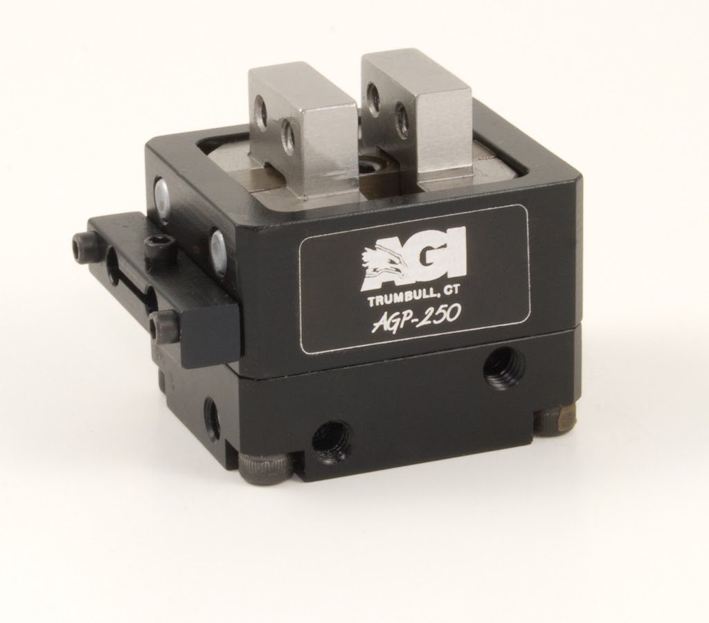
The spreading jaws have a stroke adjustment set screw (10-32) can be replaced easily with a longer one to reduce the stroke to as little as .001 inch if needed. The spreading and ejection actions are controlled independently of each other, closing and retract positions are non adjustable.(Note: Be sure to avoid all sharp edges during installation as exposed threads or corners can harm the ring during the assembly process.)
When it comes to designing your tooling most application can use a straight forward tooling design were all the jaws are the same height.
Tooling design should include call-outs for corner breaks, radii and the prevention of sharp edges that can nick or gouge the ring during pick and place assembly. Tooling length guidelines can be found on the technical data sheets for each unit. Cross section, the durometer of compound, diameter and tooling jaw length all play a part in selection of the correct gripper. Gripper tooling should never come in contact with the dead nest or part the o-ring is being installed on, any contact will reduce the useful life of the o-ring gripper and tooling.
Controlling O-Ring Placement
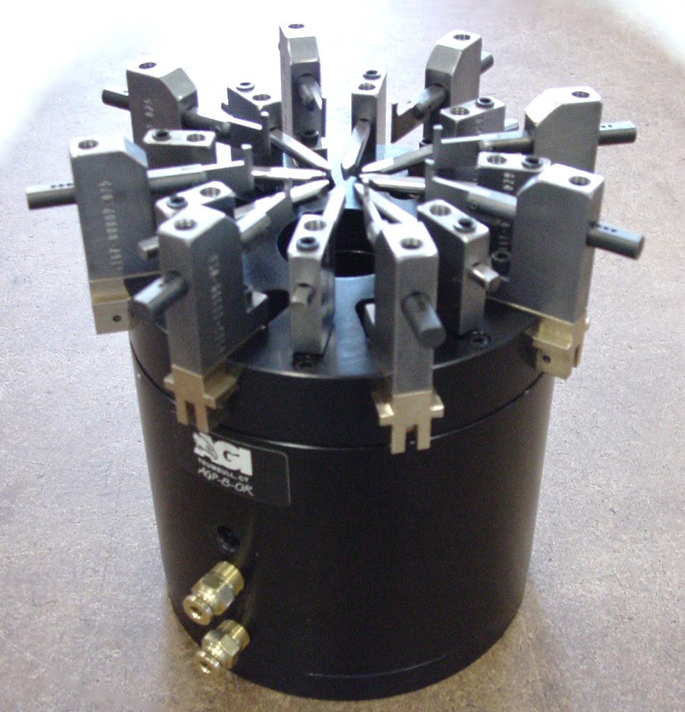
In some applications, controlling o-ring placement becomes difficult. A suggested method of dealing with this is to step the spreading tooling jaws. (Of the six jaws every other spreading jaw will be shorter than the others, usually only shorter by the cross section of the o-ring.) Note: Your dead nest will have to accommodate the three longer jaws in the dead nest. In this manner, when the ejector jaws are actuated they push the o-ring off the first three spreading jaws, forming a triangle. The three sides will then be locked into the grove of the part. The ejectors then push the o-ring off the remaining jaws, completing the process. A flow control should be used to fine tune the ejection speed for a controlled release. The o-ring no longer snaps from all the fingers at once, but instead achieves a reliable process.
When small batch runs or quick change over is needed adjustable tooling can be useful, see picture below.
Standard tooling design by AGI offers a quick starting point; this drawing can be modified to fit your application and is the best way to make your tooling to fit the job. Tooling steel should be used make the spreading and ejecting jaws. Steel is a much better material than aluminum for making jaws since the aluminum will wear quickly and tends to develop burrs. When this occurs the o-ring or seal tends to roll instead of slide off tooling. Some engineers also like to coat the tooling with Armoloy to reduce the friction between the tooling and the rubber.
When yet in the R&D stage, investing in finished tooling can be cost prohibitive, but there are some simple ways to produce tooling jaws for prototyping. The first is to make aluminum blanks with the jaw mounting pattern on it, then press steel dowels in it that will be used as the o-ring spreaders. The second quick fix is to turn the profile on the lathe. Once the height and contour are correct, they can be sectioned into equal parts using a wire EDM or slitting saw.
Two different valves will be needed, one for the spreading jaws and the other for the ejector. The spreading jaws are double acting and will need a 4 way 2 position valve. The ejector jaws are single acting spring return and will require a 3 way 2 position valve. Other items needed are an air supply, controller, valves and fittings.
3D cad, Solidworks, Step and Iges files are available on our web site. Download CAD Files
To learn more concerning our assembly automation components, please contact us and we will help with your application needs.